Do you have a radar detector but don't like how it looks sitting on your dash or visor? Maybe you live in a location where radar detectors are illegal? Well, here is a little write-up I did for a stealth install of my radar detector.
DISCLAIMER: This modification is to be followed and used at the sole risk of the individual performing it. When performing any modifications, there will always be the risk of damage to the car. MODIFY AT YOUR OWN RISK. Read the procedure carefully and be sure that you feel comfortable with the modification before you begin. Now on to the fun stuff!!
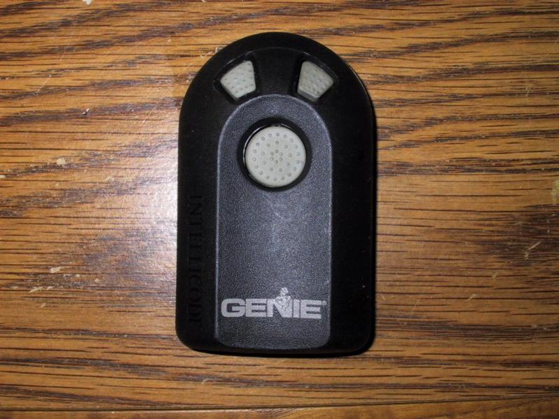
Garage Door Opener Remote: This is the original garage door opener remote. The garage door opener is made by Genie and this particular unit has the Intellicode code hopping security feature. Opening the remote was easy and involved removing a few screws on the back of the case.
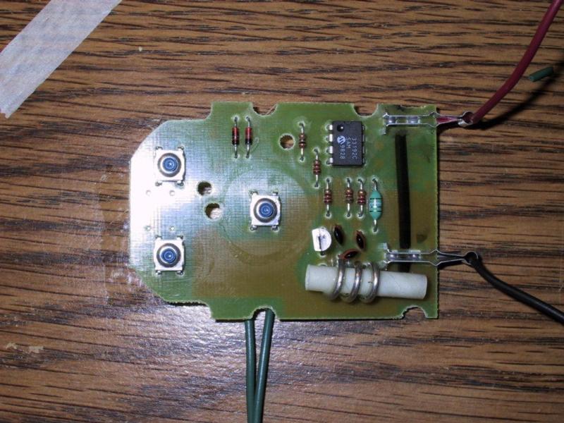
Garage Door Opener Remote Circuit Board (Top): This is a shot of the actual circuit board inside the case of the remote. The center blue button is the one I tapped for use in the car. The wires you see are what I soldered to the circuit board and will be discussed in more detail later.
Garage Door Opener Remote Circuit Board (Bottom): This a bottom shot of the circuit board. Again, the wires I soldered to the circuit board will be discussed a little later.
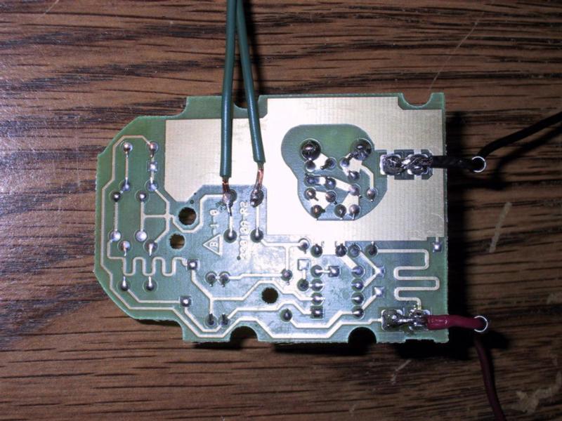
Soldered Leads to New Switch: This is a close up of where I soldered the two wires for the push button switch that I used. Not the prettiest soldering job, but it works. The push button I used simply shorts the same contacts as the button on the remote. Be careful not to burn the circuit board when applying the solder.

Soldered Power Leads to Circuit Board: This is a close up of where I soldered the leads that would power the remote from the car. This is not necessary, since a battery would still work, but I did not want to pull the dash apart every time I needed to change a battery. This particular remote was a 12 volt remote. If you are trying this with a remote that requires 9 volts an added circuit will be required to provide the proper voltage from the car. Be sure to pay attention to the polarity of the leads. I also ended up using the battery terminals as wire guides for added support to the soldered power leads, an unexpected bonus!

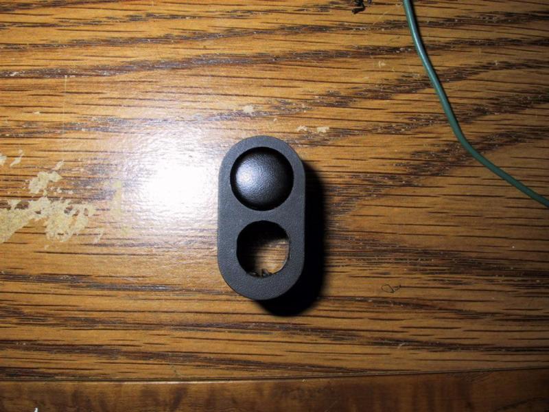
Fog Light Switch Assembly: The location I mounted my new switch was just below the fog light button. This is a shot of the fog light switch assembly removed from the headlight switch/vent assembly (prior to the installation of the new garage door opener switch), it will pop out. The lower portion of the switch assembly is actually hollow and will be drilled to mount the new switch. Removal of the headlight switch/vent assembly is discussed a little later.

Fog Light Switch Assembly Taken Apart: This is a shot of the switch assembly taken apart prior to drilling. You will notice 4 tabs that hold the switch assembly together. Use a small, pointy object to slowly and carefully pry the switch apart. When it comes apart, there will be two tiny springs that will come out. Don't lose these springs since they are required for the fog light switch to function properly. When putting the switch back together, re-insert the springs and carefully snap the assembly back together, verifying proper fog light switch mechanical operation.

Another Shot of the Fog Light Switch Assembly: Here is another shot of the fog light switch assembly taken apart to show where I will drill the hole to accept the new switch for the garage door opener. The top part is the existing fog light switch. The bottom is where I will be drilling the new hole. Notice the location of the two springs mentioned earlier. This is where they need to be prior to fog light switch re-assembly.

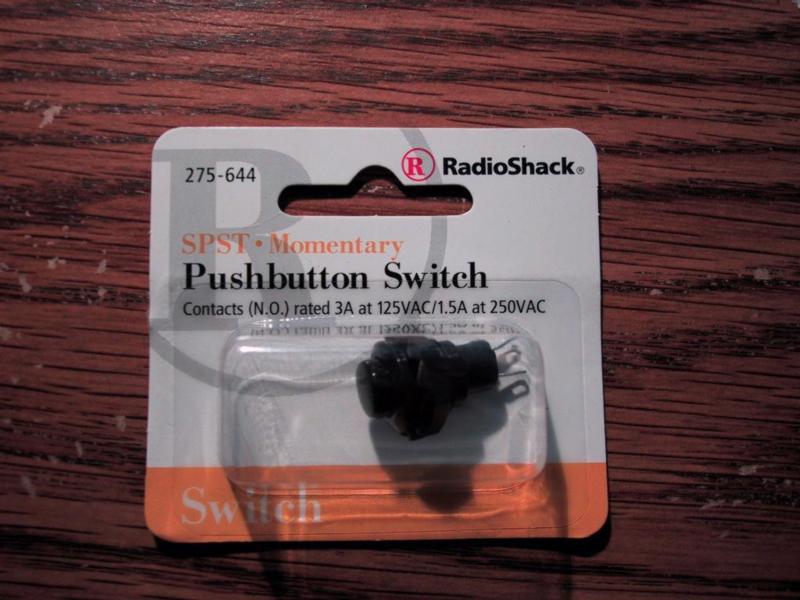
Switch Used for This Install: This is the switch I used for the install. It is a simple push button type switch. The cost was less than $2 from Radio Shack.
Fog Light Switch Assembly After Hole Was Drilled: This is a frontal view of the switch assembly after it was drilled. I used a Dremel Tool for this, slowly widening the hole. Be sure to take it slow and check for proper fit of the switch as you go along. You don't want to make the hole too big for the new switch.
Circuit Board Inside the Dash: This is the circuit board installed inside the car (the area behind the headlight switch/vent). I used some velcro to keep it in place in there. To remove the headlight switch/vent assembly, there is a screw that is directly beneath it on the dash (you can't miss it). Once the screw is out, gently pull the headlight switch/vent assembly out. Before you can pull the assembly out entirely, you need to disconnect the harness to the headlight switch (round) and the fog light switch (square, it is visible in this picture).

Routing of Switch Wires: On the fog light switch harness, there are two unused holes. Route the wires for the new switch through these holes as shown. The power lead (red) was spliced to a constant 12V power source and the ground lead (black) was spliced to a ground wire. Both wires were on the headlight switch harness (constant 12V - red/white wire, ground - brown wire). Be sure to verify your wire colors for your car. You can also see the circular harness for the headlight switch in the background.

Headlight Switch/Vent Assembly Back in the Dash: This is a shot of the headlight/vent assembly back in the dash with the wires for the new switch hanging out. I decided to keep the excess slack to make future removal of the headlight/vent assembly easier. To reconnect the headlight switch harness, I found it easier to remove the headlight switch form the assembly. To do this, remove the outer switch cap by pulling towards you. Once the cap is off, you will notice a nut. Unscrew the nut and remove the headlight switch. Reconnect the harness and re-install the headlight switch (of course, don't forget to reconnect the fog light switch harness!).
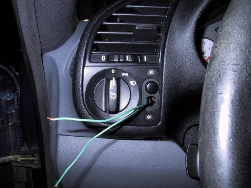
The Finished Product: Here is the finished product. I soldered the end of the leads to the new switch. I then pushed back the excess wire into the dash and snapped the switch into the fog light switch assembly. Now go play with your garage door opener!

About The Author
jmciver
Original site at:
http://www.vb.quik.com/jmciver/pages/garage.htm
Tekið af slóðinni
http://www.bimmerdiy.com/diy/garageopener/